10 years

ST8

The handiest anchor to work with.

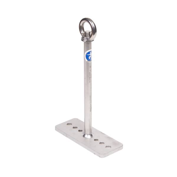
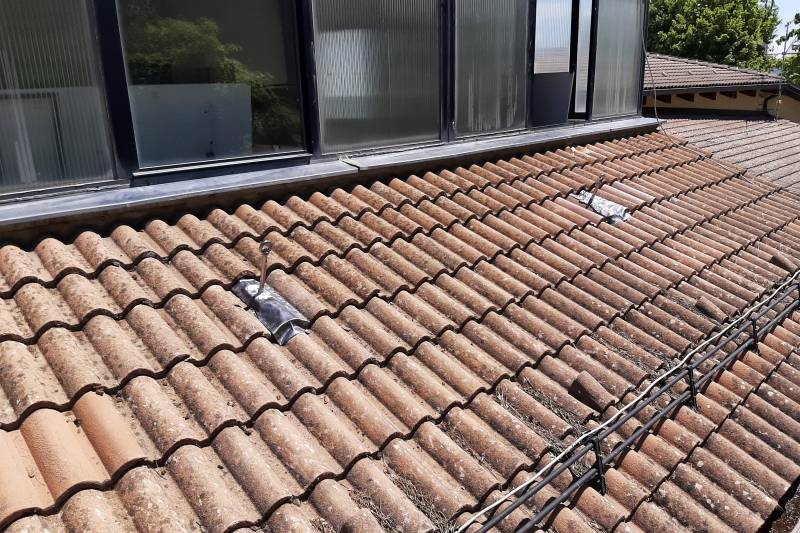
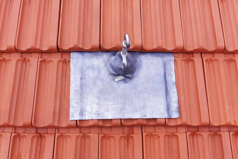
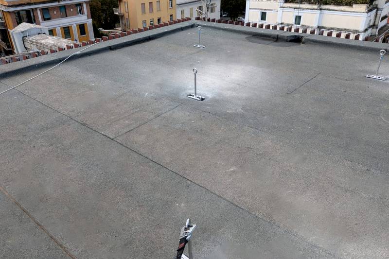
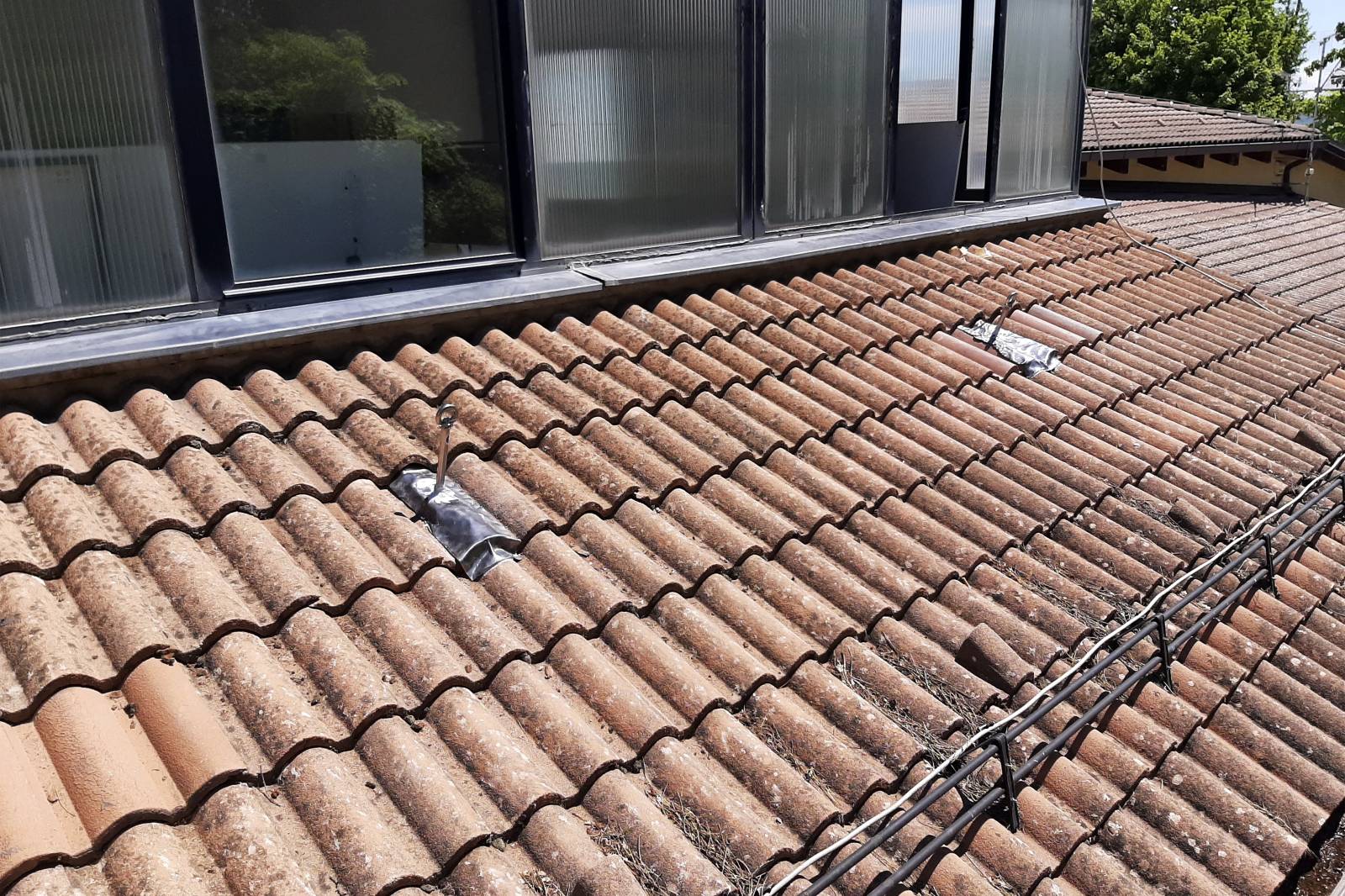
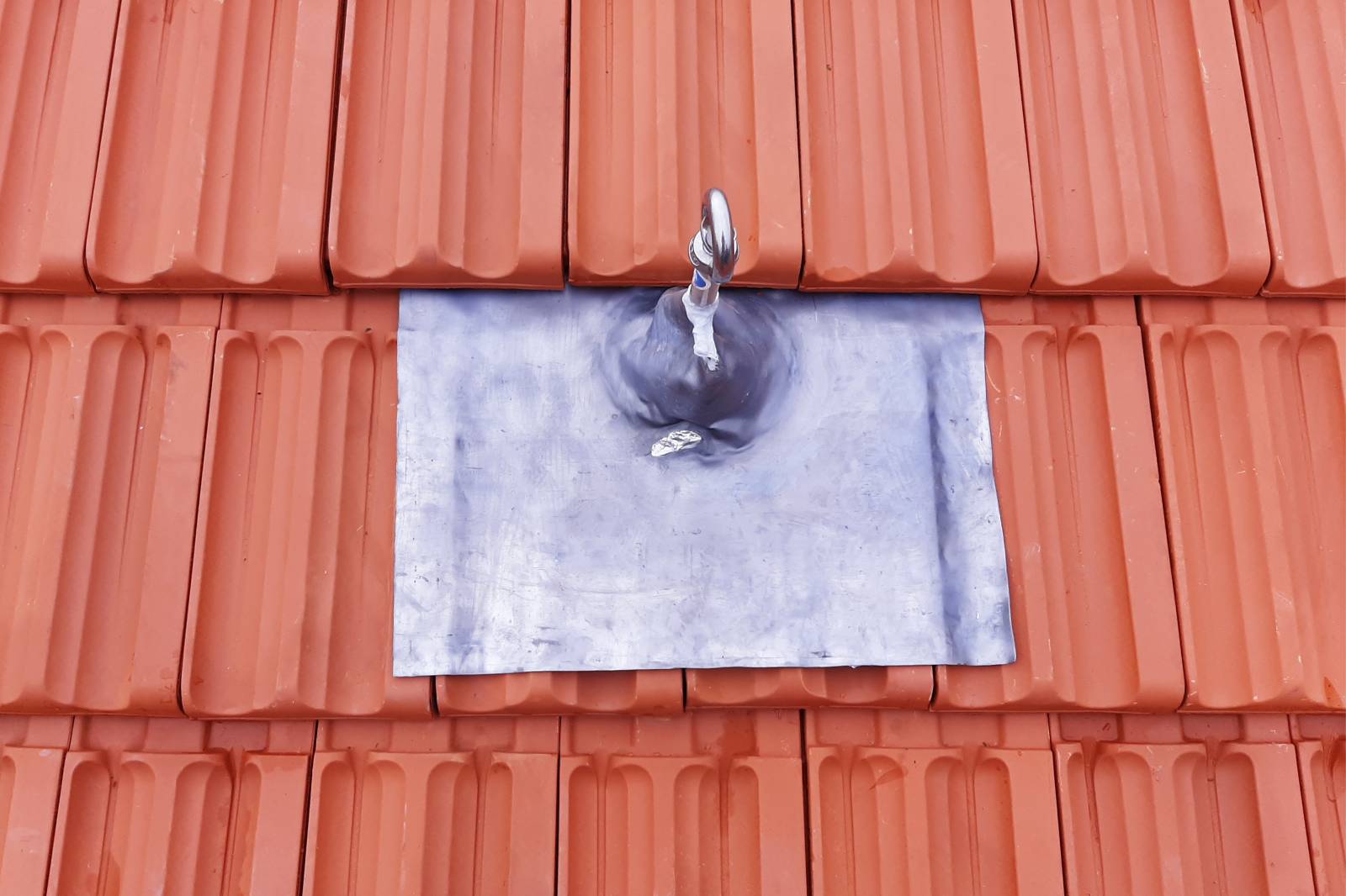
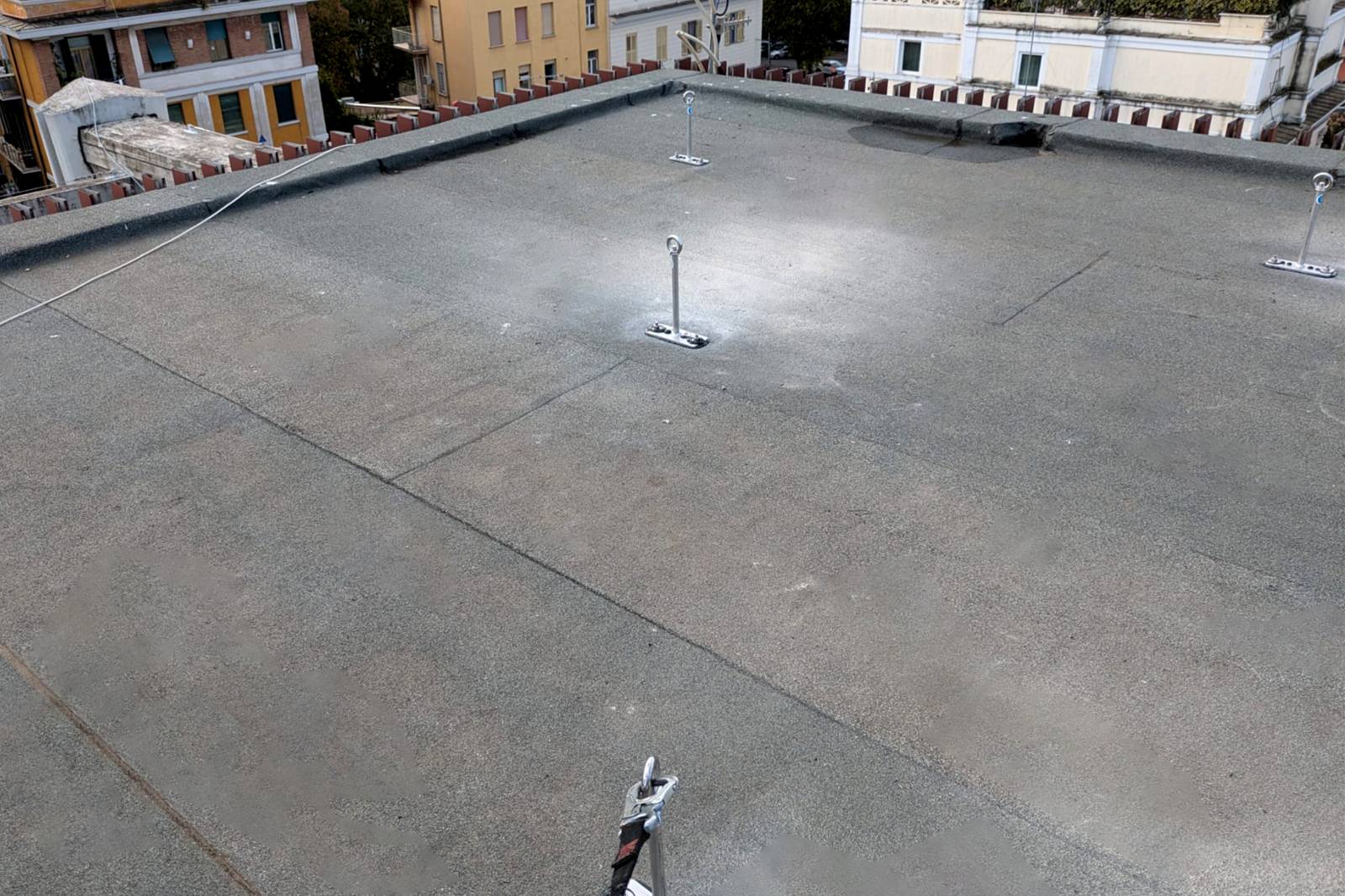
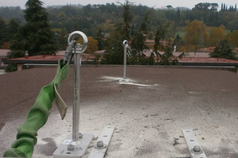
The ST8 fixed anchoring device is the ideal solution for eliminating the pendulum effect in gable roofs, ensuring safety and stability. Designed to last, it is made entirely of pickled AISI 304 stainless steel and certified according to current regulations.

  • Ideal for gable roofs: avoids the pendulum effect
  • Available in two heights: 30 cm and 50 cm
  • Made entirely of pickled AISI 304 stainless steel
  • Certified according to UNI EN 795:2012, UNI CEN/TS 16415:2013 and UNI 11578:2015 standards

By consulting the downloadable manual below, you can obtain further information on choosing the fastening method for your devices and on the responsibilities imposed by current legislation.

Product
001483
Template
SS h30 ST8 pole
Details
Anchor device EN 795 class A, shaped as a h30 cm pole. Semi-swivel eyebolt at the end. Manufactured in 304 pickled stainless steel.
Product
001575
Template
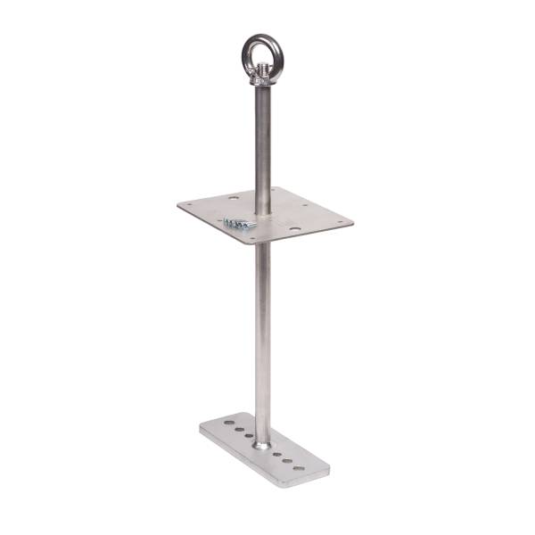
SS h50 ST8 pole
Details
Anchor device EN 795 class A, shaped as a h50 cm pole. Semi-swivel eyebolt at the end. Manufactured in 304 pickled stainless steel.
Product
000196
Template
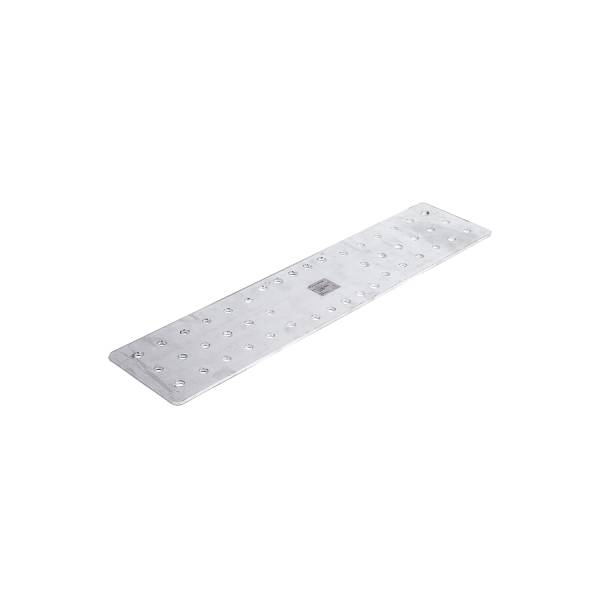
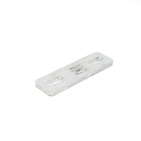
GV Plate 200X60
Details

Galvanised Slotted Plate 200X60

Product
000039
Template
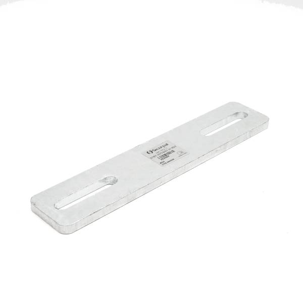
GV Plate 300X60
Details

Galvanised Slotted Plate 300X60

Product
000203
Template
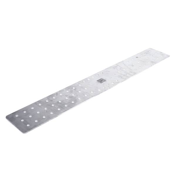
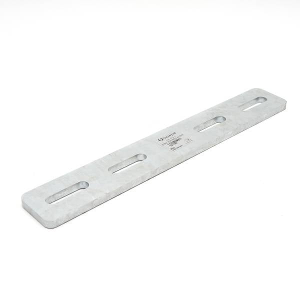
GV Plate 400X60
Details

Galvanised Slotted Plate 400X60

Product
000211
Template
STC plate 66cm
Details
Beam plate 66 cm STC/ST8
Product
000212
Template
STC plate 100cm
Details
Beam plate 100 cm STC/ST8

FAQ ANCHORS.

There are many possible fastening methods, each closely related to the type of structure on which the anchoring system is installed. They can be secured using a plate and counterplate, screws and nuts, or using rods and two-component resins, wood screws, mechanical anchors, rivets, clamps, etc. However, it remains the responsibility of the engineer in charge to verify the type of anchor and the structure and indicate its characteristics and dimensions.

Anchor points allow movement only in a circular area with a radius equal to the length of the lanyard, while lifelines allow linear movement along their entire length.

The warranty period for anchoring devices is determined by the manufacturer. Therefore, while it can be said that the most resistant products are those made of pickled or electropolished AISI 304 stainless steel and AISI 316 stainless steel, it's impossible to provide a definitive answer.

The durability of devices depends on a series of factors including the material, the use made of them, the technical characteristics, the atmospheric conditions to which they are subjected, etc.

Yes. In fact, UNI 11560:2022 requires that the interval between two periodic inspections (whether visual or instrumental) be no greater than 2 years for checks relating to the anchoring system and 4 years for checks relating to the supporting structure and anchors.

Yes. According to UNI 11560:2022, point 9.2.1, the system inspection after assembly must be performed by the installer and conducted in accordance with the instructions of the device manufacturer, the anchoring system designer, and the structural engineer. For anchors with the insertion of mechanical or chemical elements, the possibility of carrying out load tests that produce a tensile force of at least 5 kN for each anchor must be evaluated to verify the correct connection between the anchor and the supporting structure.

Yes. Since the purpose of an anchoring system is to connect the lifeline to a personal protective equipment (PPE) system to prevent falls from a height, a risk assessment must be performed prior to its design. This assessment involves analyzing the prevailing, concurrent, or subsequent risks and/or those associated with the work/activities to be performed on the roof.

It must necessarily be taken into consideration in order to design a system that protects the worker from such risks.

Pursuant to Article 59 of Legislative Decree No. 81/2008, liability lies with the worker if he or she fails to comply with safety obligations, observe personal protection provisions, use work equipment correctly, or participate in training programs.

In the event that the malfunction of one or more parts of an anchoring system is instead attributable to manufacturing or installation defects, the responsibility falls on the manufacturer and/or the installer.

According to UNI EN 795:2012, point 3.2, an anchoring device is a point to which to connect the PPE making up the personal protection system against falls.

According to UNI EN 795:2012, point 3.6, an anchor point is the point on an anchorage system to which the personal fall protection device is intended to be fixed.

To simplify, the anchor point is the physical part where the connector attaches.

UNI 11560:2022 indicates that the documentation to be provided to the client must contain:

  • Anchoring system configuration design (Technical Information for System Use), carried out by the anchoring system designer on the basis of the risk assessment.
  • Structural designer's verification project relating to the type of anchor to the supporting structure based on the type of material of the structure (Calculation Report).

According to Appendix A2 of UNI EN 795:2012 – Guide for documentation to be provided after installation, the necessary documentation that must be provided to the customer must include:

  • Schematic installation plan showing the address and location of the installation, the name and address of the installation company, the name of the person responsible for the installation, product identification (name of the anchor device manufacturer, type, model/article), fixing device (manufacturer, product, permissible tensile and transverse forces), schematic installation plan and relevant information for the user/client, such as the arrangement of the anchor points.

This plan should be posted at the entry point to the building so that it is visible or available to everyone.

  • Declaration of correct installation provided by the responsible installer, which must contain the following information regarding the anchor device: declaration of conformity of the installation with the installation instructions provided by the manufacturer in the use and maintenance manual, declaration of execution according to the installation plan, referred to above, declaration of fixing to the specified substrate and in the specified manner (number of bolts, correct materials, correct position, correct location), declaration that the work was commissioned in accordance with the manufacturer's information, photographic information/documentation.
  • Declaration of conformity of materials and instruction manuals for assembly, use and maintenance, issued by the manufacturer of the anchoring system.

The pendulum effect is one of the major risks present in roofing, especially at corners. UNI 11158:2015 distinguishes between the pendulum effect on linear or point anchors:

  • The pendulum effect on a linear anchor is the translation of the worker on a flexible linear anchor with consequent oscillation with respect to the linear anchor following a fall from a height that occurred at an offset from the centerline of the linear anchor.
  • The pendulum effect on a point anchor is understood as the oscillation of the worker with respect to his anchor point following a fall from a height that occurs at an angle to the line passing through the anchor point and perpendicular to the edge of the fall.

The Consolidated Law on Health and Safety in the Workplace, Legislative Decree 81/2008, defines safety signs as an integral part of the prevention and protection measures to be implemented to control one or more risks in the workplace. The same decree establishes the criteria for selecting signs and their characteristics.

When a roof or installation has a fall protection system that can be used by workers, it must be appropriately marked.

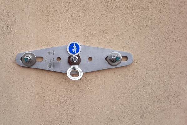
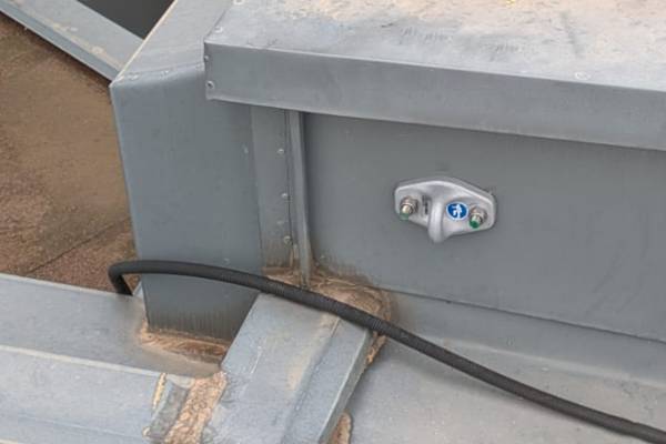
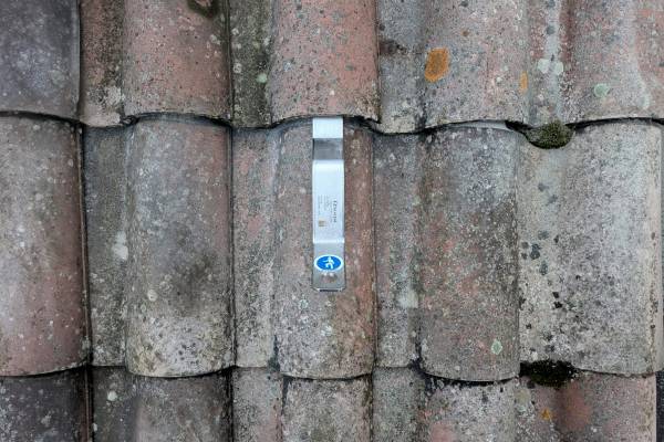
The individual anchor points are indicated by a mandatory label/sign, i.e. a white pictogram on a blue background that categorizes them as anchors.

Lifelines are instead indicated by a sign that must be placed near the roof access point: it must contain the installation date and requirements relating to the system's use (such as the mandatory use of safety harnesses and/or lanyards, the maximum number of workers that can be connected to the line, etc.).

Highlights

References.

Related items

Other products from the same line

Infinity line

Anchor devices ideal for wall installations.

Fusion

Aluminum and steel anchors suitable for rope work

STC

Anchor suitable to be installed under rooftiles.

Plam

Anchorage point for trapezoidal sheet metal.

Ask for more information

* Obligate fields
*
Newsletter
Sign up and stay updated on courses and new products for your safety.
* Obligate fields
*
*
Telephone +39 059 81 81 79
Registered and operational headquarters Via dei Mestieri 12 - 41030 Bastiglia (MO) Italy
SOCIAL
Scroll